Hi Tom,
Happy New Year!
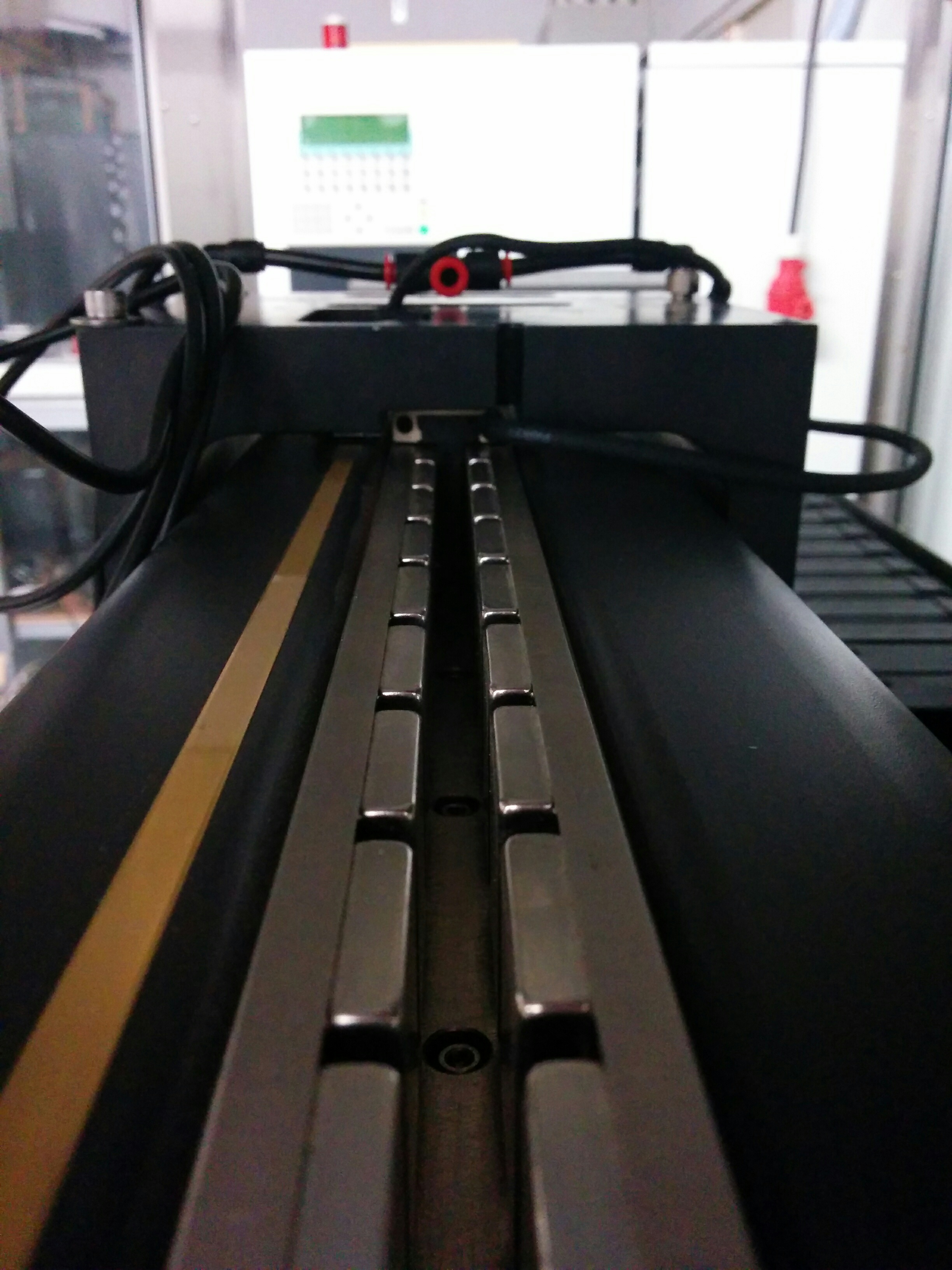
I've got a question about SnapAmp. Currently I'm trying
to get the Kflop/SnapAmp working for a system with linear
motors and encoders (see photo).
The incremental encoders (renishaw) have a resolution of
0.1 microns per pulse and their position can be read
without problems by the encoder inputs of the SnapAmp
using the A-A+ and B-B+ outputs of the encoder. The
encoders do NOT give out a Z-Z+ index signal. The linear
3-phase motors have 6 different wires for the coils (and
two for a Hall sensor), so the coils are separately wired,
each coil has a resistance of 20 Ohms.
If I make one complete 360 phase revolution, the motors
move approx. 60mm. From this I can calculate that the
invDistPerCycle would be 1.66666E-6. however, I cannot get
them to work correctly. The AutoPhaseFind program is not
useful, since it requires a Z-signal from the encoder. So
I cannot set a CommutationOffset, which is probably not
useful anyway. Im running a power supply at 70V and tried
to wire the Servo's in Star and Delta configuration. Both
give sort of the same problem: generally a servo does not
get locked when activated or is instable when pressed
against (it then moves to a position a few tens of mm
away). However, sometimes when I activate the motor in a
specific position by using the axis screen (with the
checkbox) the motor suddenly locks and can be accurately
moved, for example using the step response window. But
when I make the steps bigger than say, 50000 pulses, or
set the speed high (for example 50000 pulses/sec) the
motor suddenly stops and generally ends up in a state
where the PWM is at a moderate or high power level, far
away from the pulse position that it is supposed to go
to.
I have no clue how to proceed, or how to get these
servo's running without a Z-index. Maybe I'm missing some
essential setting or insight. So any help on how to get
the servo's running is highly appreciated.
Best regards,
Jeroen